
 English English
 Views: 0 Author: Site Editor Publish Time: 2026-07-15 Origin: Site


High-risk vertical access applications demand absolute reliability. You suspend heavy loads and personnel across hazardous industrial work sites daily. An industrial safety lock serves as the crucial final fail-safe in these environments. It catches falling platforms before gravity takes over completely. However, improper installation directly triggers catastrophic equipment failure. You also face severe liability and immediate safety compliance violations. A single misaligned bracket can completely bypass the mechanism designed to save lives. You cannot rely on basic mechanical assembly or guesswork during setup. A truly successful deployment demands much more. It requires rigorous pre-checks, precise alignment techniques, and strictly documented drop-testing. In this comprehensive guide, we explore exactly how to evaluate your equipment properly. You will learn the correct steps to execute a flawless installation. We also cover how to conduct proper dynamic testing. You will secure your site and guarantee reliable fail-safe operation every time.
Evaluating your specific application dictates the choice between centrifugal and overspeed mechanisms.
Proper installation relies heavily on the exact matching of wire rope diameter to the internal friction components of the safety device.
Mandatory dynamic testing must be completed and documented prior to commissioning any suspended platform or elevator system.
Environmental factors (debris, lubrication) are the leading cause of post-installation lock failure and must be mitigated during setup.
Successful installation begins long before you mount the hardware. You must evaluate the physical environment and confirm component compatibility first. Rushing this phase leads to critical mechanical failures under load.
You must establish clear load requirements before unboxing any unit. Review strict compliance benchmarks early in your planning phase. Document the maximum safe working load for the entire hoist system. Ensure the physical environment supports safe, continuous operation. Evaluate potential extreme temperature variations or corrosive chemical exposures on site. These environmental factors heavily influence device performance.
Never underestimate the vital importance of your steel cables. The braking mechanism relies entirely on this specific component. Follow these critical inspection steps before installation:
Verify the exact cable diameter matches your lock specifications perfectly.
Inspect the structural integrity for any broken wires, bird-caging, or severe kinks.
Check the entire length for excessive manufacturer lubrication or aftermarket grease.
Heavy grease severely degrades emergency lock engagement. It reduces essential internal friction between the clamping jaws and the cable. A clean, correctly sized cable ensures a rapid stop during an emergency.
Evaluate your main hoist frame and mounting brackets for hidden stress fractures. The anchor point absorbs massive kinetic energy during a sudden dynamic load stop. Weak anchor points will shear instantly under extreme force. Use non-destructive testing if you suspect any metal fatigue. Verify the bolt hole patterns align perfectly without forced bending. Proper mount integrity ensures the device actually holds when triggered.
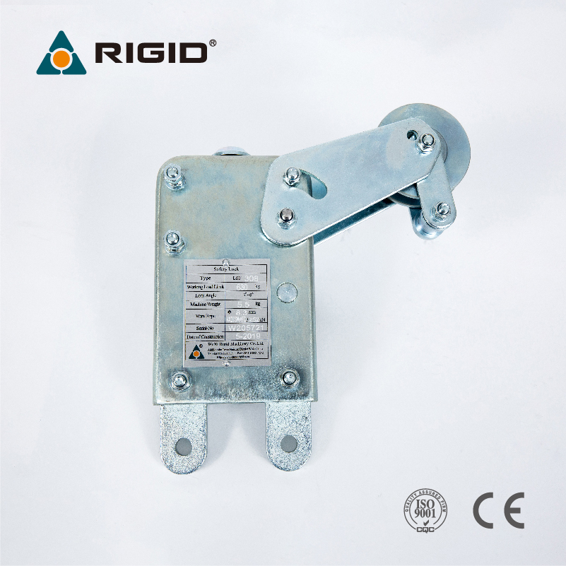
Different industrial applications demand highly specific locking mechanisms. You must choose the right design to protect your crew and equipment. A mismatch between device type and operational conditions causes fatal accidents.
We use a simple decision framework to categorize these critical devices. A Centrifugal Anti-Fall Safety Lock engages based on the rotational speed of its internal components. Centrifugal force pushes internal friction blocks outward to grip the rope. In contrast, an Overspeed Safety Lock triggers via direct downward velocity limits. It clamps shut instantly when the descent speed exceeds a pre-set threshold.
Feature | Centrifugal Mechanism | Overspeed Mechanism |
|---|---|---|
Trigger Method | Internal rotational speed exceeds limits | Direct downward velocity exceeds limits |
Primary Use Case | Standard construction hoists | Heavy-duty suspended platforms |
Engagement Feel | Gradual braking force application | Instantaneous hard clamp |
Sensitivity to Sway | Moderate sensitivity | High sensitivity to sudden drops |
A Suspended Platform Safety Lock requires precise dual-hoist synchronization. It must also provide strong resistance to platform tilt. If one hoist fails, the anti-tilt function keeps the work basket perfectly level. Conversely, an Elevator Installation Safety Device focuses heavily on high-load environments. These heavy-duty applications demand stringent fail-safe redundancy. They operate continuously and require robust internal components to handle repetitive stress.
Always confirm valid manufacturer calibration certificates before installation. The documents must match your operational load class exactly. Never use uncertified or mismatched components for life-critical support. Check the expiration dates on all factory testing certificates. Regulatory bodies reject expired components during routine site audits.
Mechanical installation requires absolute precision. Follow these phases sequentially to ensure maximum system reliability.
Position the unit precisely according to the stamped directional arrows. You must ensure the gravity orientation is completely correct. Upside-down mounting guarantees total mechanical failure during a fall event. Align the entry and exit guides perfectly with the exact hoist path. Careful alignment prevents dangerous cable chafing over time. Apply the manufacturer-specified torque to all mounting bolts using a calibrated wrench. Mark each bolt head using a brightly colored tamper-evident torque seal. This visual seal helps inspectors verify proper tightening at a glance.
Safely thread your designated secondary cable through the upper guide block. Pass it slowly and deliberately through the internal locking mechanism. Maintain adequate manual tension during this entire threading process. Proper tension prevents internal snagging or premature triggering during initial setup. Secure the lower end of the rope using the appropriate tension weights. These heavy weights ensure the steel rope remains perfectly taut. A tight cable travels cleanly through the Wire Rope Safety Lock housing. Insufficient bottom weight causes dangerous cable slack.
Many modern systems require a direct interlock between primary and secondary devices. Connect the electronic or mechanical trip-switches to the primary hoist control board. These connected switches automatically cut main hoist power if an emergency stop occurs. You must also ensure any tilt-sensing levers remain totally unobstructed. Check them manually to confirm a full range of motion. Any debris blocking these exterior levers will disable the anti-tilt function entirely.
Mechanical assembly represents only half the job. Rigorous dynamic testing proves the system actually works under stress.
You must perform a mandatory simulated free-fall test prior to commissioning. Introduce a simulated slack-rope or overspeed event deliberately. This controlled drop forces the mechanism to engage under real-world physics. Keep all non-essential personnel clear of the equipment during this testing phase. Conduct this test close to ground level to minimize extreme risk.
Measure the exact stopping distance immediately after the engagement event. Verify this critical measurement falls within strict regulatory thresholds. Usually, this requires less than 100mm (or 4 inches) of total travel. A longer stopping distance indicates severe internal component wear. It may also indicate improper cable sizing or excessive surface lubrication.
Carefully unload the device after a successful drop test. Reset the internal mechanism exactly according to the operational manual. Closely inspect the secondary cable for any severe crush damage. Engaging the hard clamping jaws often deforms the outer wire strands. Replace the entire cable immediately if you detect broken wires or severe flattening.
Log the specific installation date and exact test results immediately. Obtain physical signatures from the supervising site engineer and the installer. Keep these detailed records readily available in the site office for audit readiness. OSHA inspectors will ask for these specific documents first upon arrival. Failure to produce them results in immediate stop-work orders.
Post-installation realities often degrade perfectly assembled systems. You must actively manage environmental risks to maintain device readiness.
Environmental debris poses a massive operational threat to these sensitive devices. Wet paint, airborne cement dust, and heavy grease easily enter the housing. This contamination significantly reduces crucial internal friction coefficients. The clamping jaws cannot grip a slippery or clogged cable effectively. Use specialized canvas covers to protect the housing during messy construction phases. Clean the entry guides daily to prevent debris accumulation.
Adverse weather creates severe challenges for suspended platforms outdoors. Cable sway from high winds often mimics a genuine failure event. This excessive sway causes frustrating false tripping during normal operation. Mitigate this issue by securing bottom tension weights properly. Prevent cables from whipping against the building facade. You should also pause all lifting operations during extreme weather advisories.
Factory recalibration operates on a strict, evidence-oriented timeline. You must send units back for certified recalibration typically every 12 months. Never attempt to disassemble or repair the internal braking components yourself. Self-servicing instantly voids all manufacturer warranties. It also completely destroys your legal compliance status. Field technicians lack the highly specialized dynamic testing rigs required for accurate calibration.
An installed device remains only as reliable as its baseline calibration. Its ultimate performance relies entirely on the structural integrity of its corresponding steel cable. You cannot cut corners during the alignment, threading, or testing phases. We highly recommend establishing a strict daily pre-shift inspection checklist for your crew. Operators must visually check for obvious housing damage and verify lower tension weights daily. Direct your procurement teams to source strictly from OEM-certified vendors. Schedule certified third-party testing immediately post-installation. This ensures absolute compliance and protects your workforce effectively.
A: Most regulatory bodies and manufacturers require a mandatory factory recalibration every 12 months. You must return the unit to a certified facility. Field servicing is strictly prohibited because it requires specialized dynamic testing rigs. Always check your local regulations for any stricter regional requirements.
A: No. You must never use the same cable. Safety standards enforce a strict requirement for completely independent primary and secondary lines. If the main hoist cable snaps, the secondary line provides the independent fail-safe required to arrest the fall.
A: False engagements usually stem from erratic, jerky hoist operation. Lack of proper lower tension weights allows the cable to bounce, simulating a fall. Additionally, incorrect rope routing or severe cable contamination can trigger the internal speed sensor prematurely. Check your tension weights first.
A: Elevator installation devices handle significantly higher load capacities. They endure continuous duty cycles and highly repetitive mechanical stresses. Furthermore, they must meet permanent installation standards rather than temporary construction codes. These units feature enhanced redundancy and heavier internal braking components to manage extreme wear.


