
 English English
 Views: 0 Author: Site Editor Publish Time: 2026-08-12 Origin: Site


Delays in high-altitude access deployment directly inflate project labor costs and extend timelines, making efficient equipment setup and rapid relocation mandatory operational priorities. Project managers and site engineers must balance the demand for rapid deployment with non-negotiable safety compliance, complex site constraints, and rigorous load capacity requirements. Sites frequently present unique structural challenges, including buildings without standard flat roofs, which demand specialized rigging solutions and precise engineering calculations.
This guide provides a technical, step-by-step framework for installing a suspended platform. We detail site preparation, modular assembly, rapid multi-floor relocation, mandatory safety testing, and criteria for evaluating equipment providers. By standardizing these deployment procedures, site teams can eliminate guesswork, reduce ground-level staging time, and ensure seamless implementation across diverse architectural profiles.
Site Preparation Dictates Speed: Proper ground leveling, structural load verification, and establishing electrical clearances (minimum 10 meters from high-voltage lines) are mandatory prerequisites that prevent mid-installation delays.
Strict Adherence to Configuration Tables: Assembly must strictly follow the manufacturer’s load capacity and configuration tables to prevent structural failure and ensure compliance.
Adaptability for Complex Structures: Specialized rigging solutions allow for safe deployment on structures without standard roofs, such as industrial silos, boilers, and bridges.
Specialized Equipment Mitigates Constraints: Utilizing specific configurations, such as a ZLP250 solo suspended platform, allows for rapid deployment in confined or structurally complex environments.
Supplier Competence is a Risk Mitigator: Partnering with a vetted suspended platform supplier ensures access to accurate documentation, innovative modular components designed for quick assembly, and responsive technical support.
Establishing a secure, compliant baseline before mobilizing any equipment to the roof or ground staging area defines the success criteria for the entire operation. Preparation dictates the pace and safety of the subsequent assembly phases. Site engineers must conduct a thorough audit of the physical environment, documenting structural capacities and identifying potential hazards that could impede the installation timeline.
Before bringing components on-site, verify the structural integrity of the building. Calculate parapet and roof deck load-bearing capacities to ensure they can support the outrigger beams and counterweights. Identify tie-back anchor points and assess the structural suitability for the suspension mechanism. The roof surface must be capable of withstanding the concentrated point loads exerted by the front and rear supports of the suspension mechanism.
For structures lacking standard roofs, address specific site prep requirements. Utilize specialized parapet clamps, tank rollers for silos, or direct structural anchoring for industrial boilers and bridges. Accurate load calculations prevent catastrophic structural failures during operation. When dealing with sloped roofs or fragile roofing materials, load-distributing spreader plates must be positioned beneath the outrigger supports to prevent surface penetration and distribute the weight evenly across the structural members.
Clear the ground installation area and ensure a level, debris-free staging surface. This prevents component damage and provides a safe working environment for the assembly crew. Implement mandatory electrical hazard mitigation by verifying a minimum 10-meter clearance from high-voltage power lines. Weather conditions must also be monitored; installation should be halted if wind speeds exceed 8.3 meters per second or during heavy precipitation.
Set up physical barricades and drop-zone warning signage around the staging and operational areas. Protecting ground personnel from potential falling objects is a non-negotiable safety requirement. The barricaded zone should extend outward from the building base, calculating the potential deflection trajectory of a dropped object based on the maximum working height.
Site Preparation Task | Verification Method | Acceptance Criteria |
|---|---|---|
Roof Load Capacity | Structural Engineer Review | Exceeds maximum point load of outriggers by 1.5x safety factor |
Electrical Clearance | Laser Measurement | Minimum 10 meters from any live overhead lines |
Ground Staging Area | Visual Inspection | Level, compacted surface free of debris and standing water |
Drop Zone Barricades | Physical Measurement | Radius equals 1/4 of the working height, clearly marked |
Rigorous pre-assembly checks prevent critical failures and costly rework during the lifting phase. Evaluating components against expected outcomes ensures the system will perform safely under load. Every pin, bolt, and wire rope must be accounted for and inspected before assembly begins.
Cross-reference delivered components with the manufacturer’s chapter on load capacity and configuration tables. Verify the correct ratio of counterweights to the platform's projected outreach and payload. Deviating from these tables compromises the structural stability of the entire system. The outreach distance—the measurement from the front support to the suspension point—directly dictates the required counterweight mass. Site supervisors must physically count and weigh the cast iron or concrete counterweight blocks to ensure they match the engineered specifications.
Audit the traction hoist suspended platform mechanisms for mechanical integrity. Check for proper lubrication and ensure there is no casing damage. Inspect primary and secondary wire ropes for kinks, bird-caging, or excessive wear. The wire ropes are the lifeline of the system; any reduction in nominal diameter exceeding 5%, or the presence of broken wires within a single strand, mandates immediate replacement.
Test the electromagnetic motor brakes and manual descent overrides prior to load application. Confirming hoist functionality on the ground mitigates the risk of mid-air mechanical failures. The overspeed safety locks must be manually triggered to verify the internal clamping jaws engage smoothly and release only when the tension is removed.
A chronological breakdown of the assembly process highlights where innovative, tool-less modular designs accelerate timelines without compromising structural integrity. Strict adherence to these steps ensures a compliant setup. The installation sequence must be executed by trained personnel wearing appropriate personal protective equipment.
Position and secure the front and rear supports of the outrigger beams according to the calculated outreach. Apply and secure the calculated counterweights to the rear support. Tension the stabilizing wire ropes and verify the outreach distance matches the configuration tables. The outrigger beams must be perfectly parallel to ensure the platform hangs level. Once the counterweights are stacked on the rear mounting pins, they must be locked in place with a securing bar or padlock to prevent unauthorized removal.
Connect the base sections, side rails, and end stirrups on a level ground surface. Leverage quick-connect pins and tool-less assembly features to reduce manual labor and achieve installation efficiently. Torque all structural bolts to manufacturer specifications where applicable. The modular sections usually come in 1-meter, 2-meter, or 3-meter lengths, allowing the crew to build a basket tailored to the specific facade width.
Lay the base plates flat on the staging ground, aligning the connection joints.
Insert the high-tensile connecting pins through the base joints and secure them with cotter pins.
Attach the front and rear balustrades, ensuring the higher rail faces the exterior drop.
Mount the end stirrups (or C-stirrups) to the extremities of the assembled basket.
Install the caster wheels for ground mobility during the setup phase.
Feed the primary lifting ropes and secondary safety ropes through the traction hoists and safety locks. Secure the wire rope terminations and install heavy counterweights at the rope ends to maintain tension. Route and secure the power supply cable to prevent entanglement during vertical travel. The power cable should be tied off to the platform structure using strain relief grips to prevent the plug from bearing the weight of the hanging cable.
Implement protocols for safely detensioning wire ropes and dismantling modular sections when moving the system. Utilize best practices for quickly relocating the suspension mechanism and platform basket to different floors or elevations to maintain continuous construction momentum. When shifting the outriggers laterally along a flat roof, the counterweights must be removed first, the beams repositioned, and the weights re-applied before any load is placed on the platform.
Tailoring the equipment choice to specific architectural challenges and operational requirements optimizes both safety and efficiency. Different project scopes require distinct equipment configurations. Standard modular baskets are highly versatile, but certain environments demand specialized access solutions.
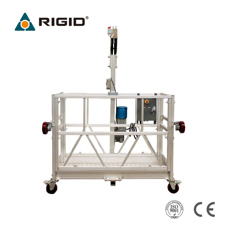
Use cases for single-person, rapid-access tasks include localized facade repair, window installation, or confined shaft work. The trade-offs involve a lower payload capacity versus significantly reduced setup time and a minimal footprint. Utilizing a ZLP250 solo suspended platform provides agility in tight spaces where standard platforms cannot operate. The single-point suspension requires a specific L-shaped stirrup and a guided wire rope system to prevent excessive spinning or swaying during operation.
Differentiate material hoists from certified man-riding systems. A man-riding suspended platform requires the integration of independent lifelines, full-body harnesses, and secondary fall arrest mechanisms. Personnel safety demands strict adherence to these specific certification standards. Workers must tie off their shock-absorbing lanyards to an independent vertical lifeline anchored to a structural point on the roof, completely separate from the platform's suspension rigging.
The critical transition from static assembly to operational readiness requires ensuring all systems perform under stress. Risk mitigation depends on thorough testing before personnel board the platform. Commissioning must be documented and signed off by the competent person on site.
Execute a static load test at 125% of the rated working load at ground level. Load the platform with test weights evenly distributed across the deck. Hover the platform 10 centimeters off the ground and hold for 15 minutes, inspecting the outriggers and wire ropes for any signs of deflection or slippage. Follow this with a dynamic load test at 110% of the rated working load, testing the hoist lifting and lowering capabilities through a full cycle of 5 meters.
Simulate a slack rope condition to trigger and verify the overspeed safety locks. This is done by manually lifting the safety lock roller or inducing a sudden drop on one side of the platform. Test the upper limit switches by driving the platform up to the striker plates on the wire ropes, ensuring the motors cut out automatically. Finally, verify the emergency stop buttons on the central control box immediately sever power to the hoists.
The choice of vendor impacts installation speed, compliance, and long-term ROI. Evaluating suppliers based on technical capability and support ensures a smoother project execution. A reliable suspended platform supplier acts as an extension of your engineering team, providing the necessary data and hardware to overcome site-specific hurdles.
Assess the necessity of comprehensive, localized assembly manuals and configuration tables. Verify the availability of on-site commissioning support or virtual troubleshooting during initial setup. A supplier providing robust documentation reduces installation errors and accelerates deployment. Manuals must include clear, legible diagrams of the electrical control box wiring and specific torque settings for all structural fasteners.
Evaluate suppliers based on the modularity and innovative design of their systems, comparing quick-pin connection systems against traditional bolted systems. Assess the supplier's inventory availability for rapid deployment versus lead times for highly customized rigging solutions for roofless structures. Standardized modular systems ship faster and assemble quicker, but complex industrial sites often require custom-engineered parapet clamps or saddle anchors that take longer to fabricate.
Supplier Evaluation Criteria | Impact on Installation |
|---|---|
Comprehensive Documentation | Ensures accurate assembly and adherence to load tables. |
Modular Design Features | Reduces manual labor and accelerates setup time. |
Technical Support Availability | Provides immediate troubleshooting during commissioning. |
Inventory Availability | Determines lead time for rapid deployment needs. |
Conduct a comprehensive site audit to determine structural capacities and identify potential hazards before ordering equipment.
Consult with a certified engineer on rigging requirements for complex or roofless structures to ensure compliance.
Request detailed technical manuals and configuration tables from shortlisted suppliers before finalizing procurement.
Implement rigorous static and dynamic load testing protocols prior to operational use.
A: Site prep requires verifying structural load capacities, leveling the ground staging area, establishing a 10-meter clearance from high-voltage lines, and setting up warning barricades.
A: Utilize specialized rigging solutions such as parapet clamps, tank rollers for silos, or direct structural anchoring systems designed by a certified engineer.
A: A minimum clearance of 10 meters must be maintained between the suspended platform equipment and high-voltage power lines to prevent electrical hazards.
A: With tool-less modular designs and quick-connect pins, a trained crew can often assemble the platform basket and rigging in a few hours, depending on site conditions.
A: Safely detension the wire ropes, dismantle the modular sections using quick-release mechanisms, and utilize caster wheels to move the basket and rigging to the new elevation.
A: Certified man-riding systems require independent lifelines, full-body harnesses, overspeed safety locks, and secondary fall arrest mechanisms.
A: Perform a static load test at 125% of the rated capacity at ground level, followed by a dynamic load test at 110% to verify hoist lifting and lowering capabilities.


